 In
December of 1987 Max moved to Montana with his family to build Varga
airplanes again. His first task was to modernize the design. The
following pictures are the result of the changes he made to the original
Varga. After the new "Montanair Spirit" was completed and
flown in September of 1988, it was decided that there was too much risk
and too little profit to proceed with production so Max returned to his
job at McDonnell Douglas in January of 1989.
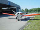
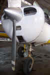
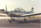
This
right front view of the Montanair "Spirit" shows some of the
changes from the original Varga model that were made to the nose of the
airplane. The spinner is a duplicate of a 14" diameter unit
used on a Piper Cherokee 180. The Varga has a 12" diameter spinner
from the Piper Cherokee 140. The "Spirit" propeller is also
the same as that used on the Cherokee 180, which is a 76" Sensenich
with a 60" pitch a 1.25" spacer. The Varga 2180 has a 76"
diameter 60" pitch Sensenich propeller without a spacer. The nose
cowl is similar in construction to the original Varga, but the
fiberglass nose bowl is Max's own design and the firewall shape was
changed to make the cowl fit better around the 0-360 180 hp Lycoming
engine.
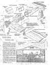
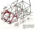 This
drawing shows the 3 inch fuselage stretch forward of the wing leading
edge. This stretching and lowering of the forward pedals 1.5"
added significantly more leg room for the pilot. The forward pedals
given a 4" adjustment range to accommodate both short and tall
pilots.
 This
left side view shows the shape of the canopy and the new vertical tail.
The original canopy frame shape was retained to make retrofitting
easier. The canopy glass was designed to be tallest at the pilots head
and the same height as the original Varga above the passengers head. The
vertical tail was moved aft more than two feet and and rudder area added
below the horizontal tail in an effort to improve spin recovery. The
dorsal fin was added only for appearance. (It should be noted that, as
certified, the original Varga WILL NOT SPIN (OK, maybe a stalled
spiral), but during Varga 2180 certification flight testing several
degrees of increased elevator travel were added and we experienced an
unrecoverable spin. The extra elevator travel was removed and spin tests
proceeded without incident.)
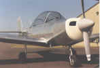
 The
left front view again shows the nose cowl, prop and spinner. The
carburetor air inlet box was installed in the left cooling air inlet and
ducted to a new carburetor heat box.
 This
close-up of the vertical tail shows the relatively large aero
counter-balance, the rudder area under the horizontal tail and the split
elevator. The aero counter-balance and elimination of the rudder
centering were intended to reduce rudder pressure, which they did. Max
left Montanair before completion of their spin testing, but his
understanding is that these modifications by themselves had little or no
effect on spin recovery with increased elevator travel.
This picture of the pilot's left side panel
shows the new throttle, pedal adjustment, and the revised flap handle.
Moving the instrument panel forward 4� allowed space to move the
throttle forward . This seemed to me to be a comfortable position and
allowed more space between the new diameter trim wheel and the throttle.
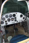
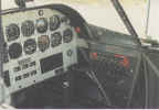 This
right side interior photo shows some of the new instrument panel, the
glare shield left by moving the instrument panel forward 4 inches, the
location of the cabin air inlet and the revised switch/fuse panel
layout. The cabin air inlet location was changed to avoid cutting holes
in the canopy glass. The new position on both sides of the glare shield
turned out to provide very good air flow to the pilot and even a little
to the passenger. The switch panel shape was changed to allow a
hinge attachment so that the panel could swing in to allow for changes
or maintenance without removing the exterior side panel. The fuses were
to be replaced with circuit breakers at a later time, but I never got to
it. The handle with the red knob was for canopy ejection.
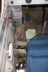
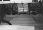 This
photo of the pilot's floor shows the relocation of the fuselage truss
side load diagonal members (to below the floor) and the two piece
fiberglass floor panel with heel wells.
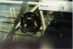 The
drive sprocket on the Montanair elevator trim control was reduced from a
14 tooth to a 10 tooth sprocket and the added trim wheel has a 3"
radius instead of the 2" handle on the Varga. This reduces
the force required for pitch trim (especially nose down) and makes finer
trim adjustments easier. One negative consequence of these changes
is that it is now possible to turn the handle 360 degrees which makes a
separate trim indicator desirable.


