VG-21
Maintenance Item # 17
9 May, 1995
FUEL
SYSTEM:
FUEL TANKS:
There is one 17.5 Gallon welded/riveted aluminum tank in each outboard wing for
as you know, a total of 35 gallons. These tanks and all their parts except the
filler neck were manufactured by Varga. The most
A leaking
sender is usually easy to fix by either tightening the flange screws or
replacing the flange gasket which is available at most aircraft supply houses.
If one of
your Curtiss CCA-1550 quick drain valves stop working, most likely you will find it plugged with
sloshing
Loose
rivets and cracked welds are a bigger problem. First make sure that red or blue
fuel residue is not just from a leaky scupper drain (see SCUPPER below). If
not, you’ll have to disconnect all attaching hardware, remove the outer wing,
drill out rivets to remove the center wing rib, loosen the tank support straps
and slide out the tank.
The rivets
are special jacketed types (P/N 44401ADJ4-5-4) installed before the end was
welded on. If you have a leaking rivet you have two options that I know of. (1 ) You can carefully grind off the weld that holds on the
end of the tank, drill out the offending rivet and replace it (lf you can find
a jacketed rivet to replace it with. We also sealed each rivet with #242 Locktite on later airplanes), clean out the sloshing
If you have
a cracked weld, clean out the sloshing
FUEL
VALVES: As you know, there is one shut-off valve for each tank. This Imperial
Eastman brass plug valve is still available from many sources including
Aircraft Spruce and Wag-Aero. Lee
GASCOLATOR:
Edo-Aire made the G199-105 gascolator
that was used on the Varga. It may still be available
from the manufacturer who bought the production rights from Edo-Aire, but if you need repair or replacement parts, I don’t
know who that is. There are other (much cheaper) gascolators
available that will work (l have one on my airplane), but none have the same attachment
or are certified on the Varga.
ELECTRIC
FUEL PUMP: This is a Facet #476087 fuel pump. I don’t know if this part number
is readily available but several aircraft supply houses sell similar Facet fuel
pumps and they may be able to get one for you. I’m not sure if another Facet
part number will work because, on the Varga, the
electric fuel pump is in parallel with the mechanical engine driven pump, not
in series, and there may be something different about this fuel pump that is
important.
FUEL VENTS:
Fuel vents are lines 1/4 aluminum tubing with 1/4 ID flexible hose at each
joint. As Lee
FUEL LINES:
All of the fuel line is 3/8” aluminum tube with standard 37 degree AN fittings and standard aircraft flexible fuel hose.
CAUTION; Replace your flexible fuel hose within 10 years or 1000 hours,
whichever
FUEL
CAP/FILLER NECK: The fuel cap is a standard unvented
fuel cap similar to those available from most Supply houses. The only problem
I’ve ever had with one of these was a bad gasket causing the cap to be loose.
The filler neck is also similar to those sold in supply houses.
SCUPPER:
The scupper is the depressed area around the recessed filler neck on Vargas. It
is there to contain and drain away spilled fuel. If the rubber hose that
couples the scupper outlet to the 114’ drain line is old and cracked, it may
leak fuel onto the tank and make you think you might have a tank leak. Check
this rubber hose first before you pull out the fuel tank.
FUEL GAUGE
SYSTEM: The fuel gauge system has apparently been a major source of
All
airplanes left the factory with a tested and functional fuel gauge system.
Every fuel gauge was inspected with a test device provided to us by Rochester
Gauges. The fuel gauges were tested at Full, 1/2 and Empty with precision
resistors and were considered to be acceptable if indicating within a tolerance
of one needle width, except at Empty, which had to indicate a maximum of Empty.
All fuel level senders were measured with a regularly calibrated precision
ohmmeter at Full and Empty positions and had to read a maximum of 0 ohms at
Empty (down) and 15 ohms + or - 1/2 ohm at Full (up). After the airplane was
assembled but before fuel was installed, the fuel gauges were read to insure
that they indicated empty. The gauges were read again when the aircraft was
filled with fuel. If any discrepancies were noted, the system was adjusted or
repaired before the airplane was delivered to a customer.
During the
certification of the Model 2180, we had to recertify the fuel system. This
included fuel tank capacity, acceptable fuel flow for the larger engine, the
amount of unusable fuel and the accuracy of the fuel gauge system. There were a
few interesting things that we discovered during this testing. One was that the
forward fuel outlet and line on fuel tank was unnecessary and perhaps
undesirable. In a steep glide angle with very low fuel, the aft fuel port would
uncover and draw air. We removed the forward fuel line on the Model 2180 but
went out of business before we made the change to the Model 2150. Another item
of interest was the fuel quantity test. When a tank was filled with fuel by
quantity, less than 17 gallons were installed, but when weighed and its weight
adjusted for fuel temperature (it was a hot spring day in
One thing
of concern to the FAA was that when the gauges finally said empty, fuel was
exhausted within only minutes. They thought (and we agreed) that the pilot
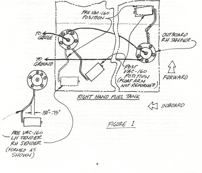
should have more time than that. On fuel systems manufactured for Varga SIN VAC16O-80 and later, two changes were made to
increase the amount of fuel left when the gauges read empty. The first was to
shorten the arm on the fuel level sender to give it less travel and more
clearance for the float at the top and bottom of its travel. In other words,
the sender float bottoms out before it gets to the bottom of the tank. The
second thing we did was rotate the tank fuel level sender mounting flange
inboard(away from each end) so that we no longer needed right hand and left
hand sending units. The effect of these changes was to reduce the accuracy of
the fuel gauge system at Empty, but give an Empty indication well before the
tanks were dry.
Early
Vargas had the same fuel gauge system that was installed on the Shinn,
including some fuel system parts built by Shinn or its subcontractors. I don’t
remember when we started to run out of Shinn engine clusters (fuel gauges) and
senders, but I believe Rochester Gauges (RG) was the only vendor that was
willing or able to make replacement parts for us. Although its been said that
there were no problems with Morriseys or Shinn’s, it
may be interesting to note that one reason we were running out of original
inventory fuel gauges and fuel level senders is because we were selling some of
them to Morrisey or Shinn owners as replacement or
repair parts.
This
continued to be a problem for Morrisey/Shinn owners
even after we switched to the RG parts because the RG fuel gauges wont fit in
the AC Spark Plug Division (AC) engine clusters, it was hard to find someone
who could repair the AC fuel gauges and a replacement RG engine cluster cost
more than $100 (the AC cluster only cost Shinn about $17), which some owners
thought was way too expensive.
GAUGES:
Fuel gauges are a part of a RG engine gauge cluster which is similar to those
used in Beechcraft airplanes and modified for use on
the Varga. They are really just 0-14 VDC voltmeters.
Early Vargas used AC Spark Plug Division engine clusters that were inherited
from Shinn inventory.
SENDERS:
The RG and
SW units are electrically identical but have some mechanical differences. The
RG senders are aluminum and the SW senders are steel. One problem we had with
the RG senders is that the floats and float arms are also different. Both types
were bought as one part number and the float arms were bent to make them right
and left hand parts. Although the RC senders were made within the tolerances
that were given, the RG floats were a little thicker and the arms had to be
adjusted to within a closer tolerance range. This meant that if the fuel tank
warped or canned too much from the welding process, the floats would sometimes
stick to the sloshing
As
designed, both fuel level senders are insulated from the fuel tank with RG #722
Nylon Grommets and a rubber gasket and are wired in series to give a total
resistance of 0 to 30 ohms. The outboard sender is grounded at its flange with
a wire running to a ground stud attached to a wing rib.
Another
problem reported by Varga owners as a NO MORE THAN
HALF FULL INDICATION (or always empty, if the wires are crossed) is caused by a
grounded inboard sending unit. The screw attaching the ground lead to the
inboard sender is much shorter than the flange attaching screws so that it
won’t touch the fuel tank when tightened all the way. If a longer screw is
accidentally installed, it will go through the gasket, touch the tank and
ground out that sending unit so that it is the only one being read (the gauge
sees 0 to 7 volts instead of 0 to14 volts).
An ALWAYS
EMPTY indication is probably a bad gauge, shorted wire to the sending units, a
shorted inboard sending unit or both sender floats stuck to the bottom of the
tank.
An ALWAYS
FULL indication can be caused by a break (open) in the electrical system (wire,
sender or gauge) or, more unlikely, by both sender floats being stuck to the
top of the tank.
Another
problem is that the senders can just wear out and be faulty by being internally
grounded shorted, giving a less than full range reading or internally open,
giving an always full reading.